![]()
![]()
HELIX ELBOW AND PIPING
THE REVOLUTIONARY HELIX ELBOW AND HELIX PIPE AMPLIFIER

How critical is pipe flow and pipe wear in your operation? It’s a very expensive problem. The amazing HELIX elbow and HELIX Pipe Amplifier piping reduces resistance and wear while increasing flow. Resistance creates excessive pipe wear, additional maintenance, unexpected downtime, additional pump wear, and uses more energy to move a given fluid.
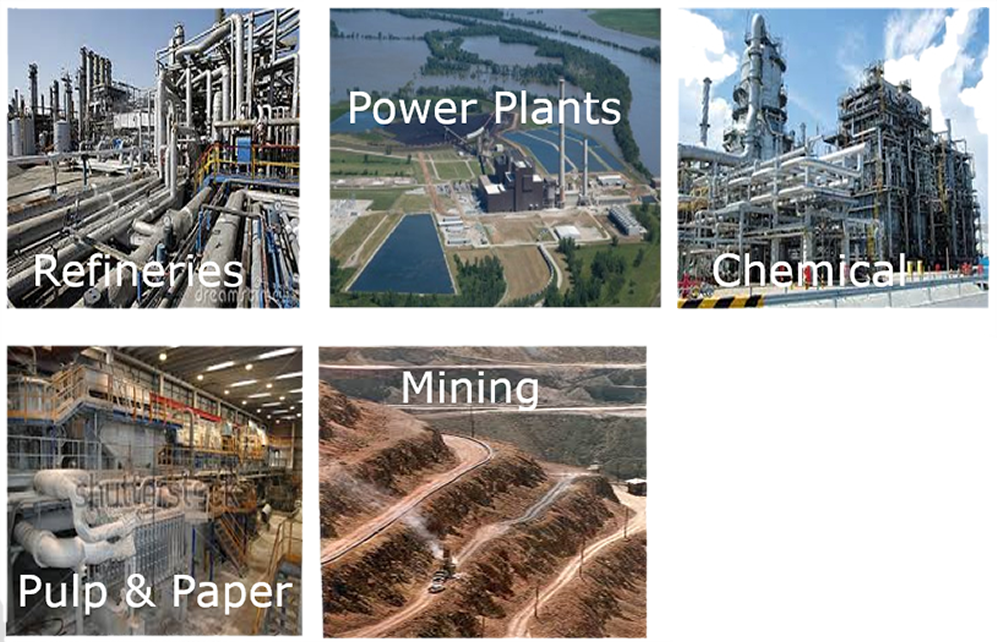
INDUSTRIES WE SERVE
- Oil Refineries
- Power Plants
- Chemical
- Pulp and Paper
- Mining
The “HELIX” design is the latest patented design that eliminates internal side wall restriction and utilizes the entire area of a pipe system.
The benefits are:
- A safer system for workers and the environment.
- No sediment build up.
- Up to 25% greater flow.
- Less pumping energy required.
- Greater life of your entire pipe network.
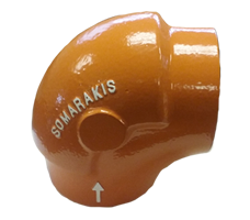
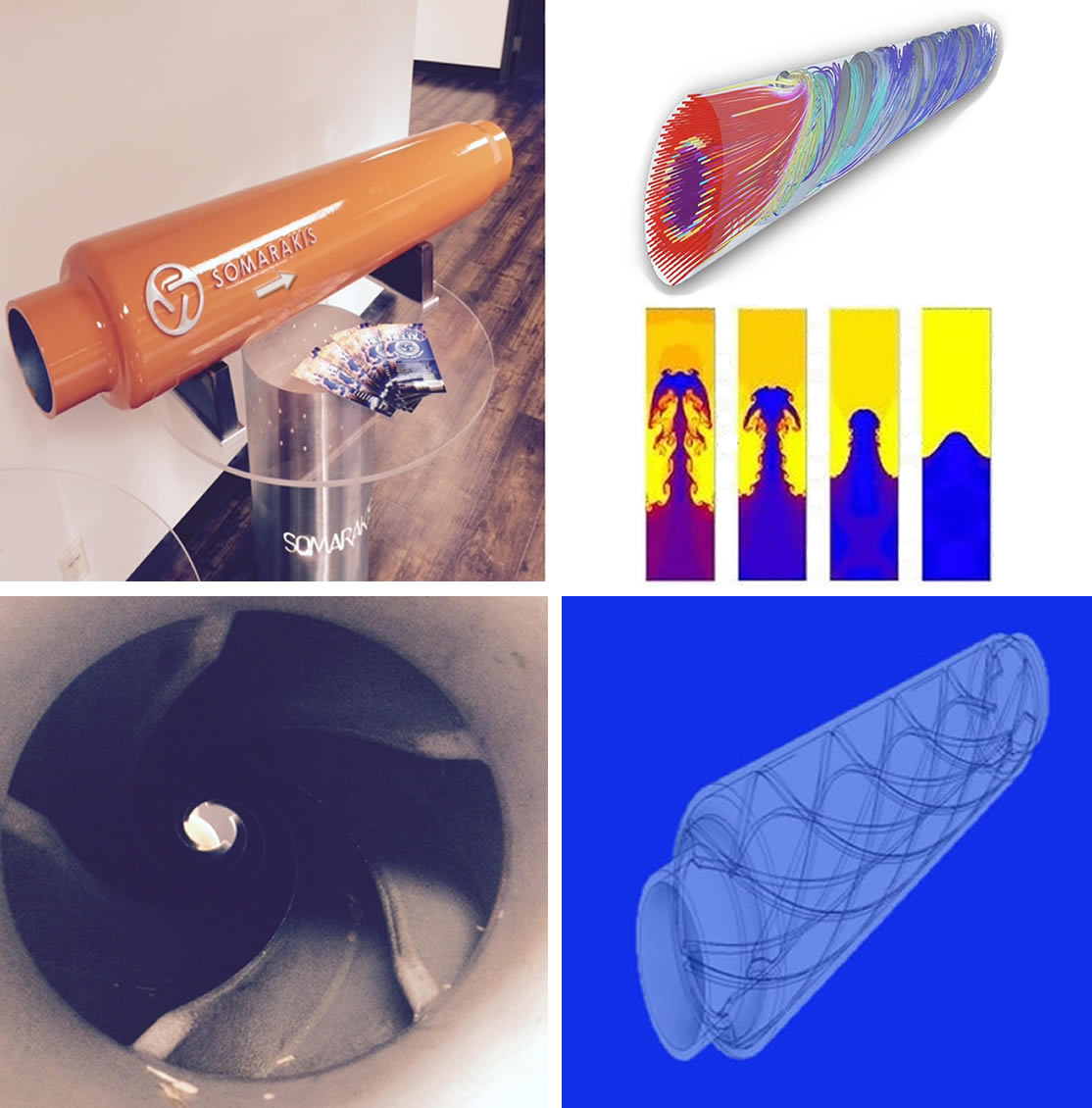
 SOMARAKIS “Helix Elbow’s”
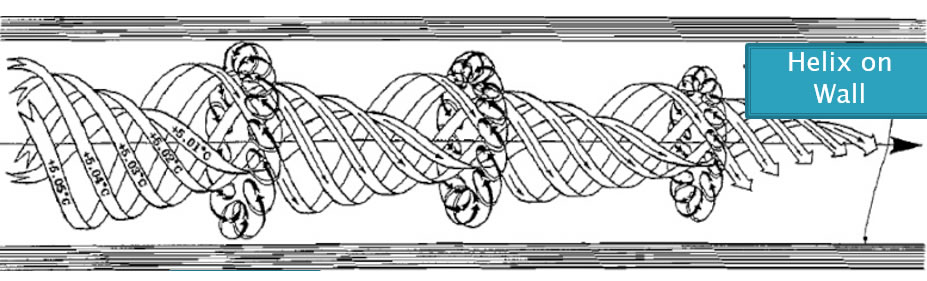
The new Somarakis helix elbow design uses the Bernoulli’s theory and uses the momentum of the fluid to overcome back pressure and creates a vortex which actually generates additional flow and decreases head loss in your fluid pipe operation.
The Helix design creates thousands of vortices spinning in each column. Depending on the pipe size, the fluids velocity, and the density of the fluid, will determine the damage to pipe structures.
Designed Components
Every fluid transfer systems uses different elbows for their unique design. We have designed our new elbows to accommodate your requirements.
- 30 Degree elbows
- 45 Degree elbows
- 60 Degree elbows
- 90 Degree elbows
- 3 Inch (76 MM) to 84 Inch (2134 MM) Diameters.
All Helix products eliminate vibration significantly. This helps prevents leaks and other potential disasters from taking place.
The proper design of the pipe line is critical, and the Helix system allows you to maximize the flows potential of any existing design. Even the worst pipe design, the flow can be enhanced to its fullest designed potential. The pipes diameter (D), operating velocity (V), particle size (d), are key factors that must be considered.
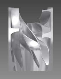
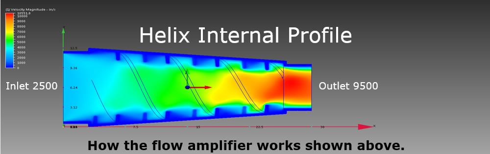
The design of the Helix system creates a phenomenon effect known as the “MAGNUS” effect. There are several channels of fluid created by the Helix. From as low as 3 Helix fins and up to 60 fins in a large diamater pipe. These create your vortex action. In each channel of fluid flow created by each series of Helix fins, the fluid is spinning unaffected by the other volumes of fluid in the same flow amplifier. As they exit the flow amplifier they join as one which is now a fully functional vortex flowing through the center of your pipe structure.
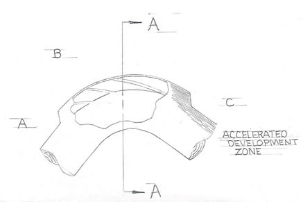
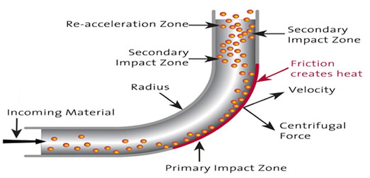
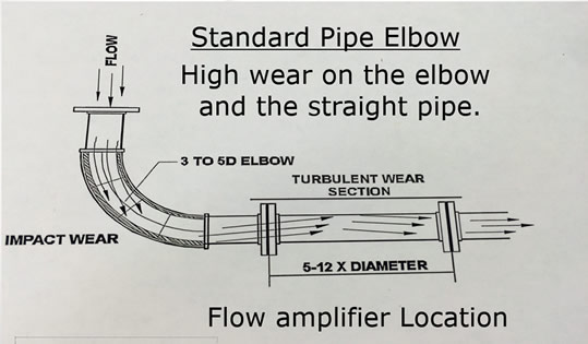
Fluid Abrasion Areas
Standard Elbow at Treatment Facility
As shown the Helix pipe system will eliminate the impact zones, reduce frictional heat, and reduce your abrasive internal pipe erosion.
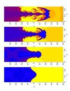
Transitional Flow Turbulence
(Helix Design) Reduces Vibration
Pipe Couplings
All of our pipe couplings are available as mechanical or a fully welded design. The mechanical couplings are available in both flange or the Victaulic design. 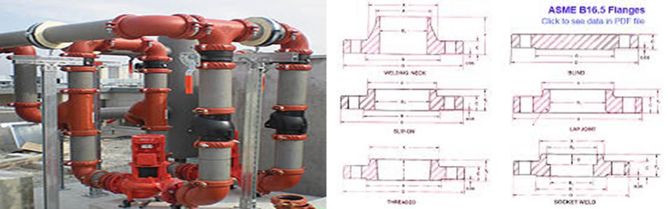
Water Resistant Design
The patented design of the helix pipe elbow fins act like tumble bars. How this works is a thin layer of material in the fluid actually collects behind the back side of each fin and fluid passing by wears against the material that has been deposited. The “Helix” fins create a vortex rotation that causes the slurry to roll through your pipe structure.
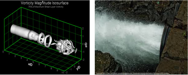
Pipe / Free Flow Velocity
Shown below is an example of gravitational flow of water through a pipe. This free flow velocity of water moving through a pipe actually generates a pulsating effect. Between each pulse is resistance to flow or back pressure which is your speed to length ratio.
Helix Reducers Profile
VELOCITY Change of Water @ 60F. / 15.5 Celsius
Shown above is a 10” to a 6” pipe reducer. It has a split “Helix” design. The fluid in the reducer generates a significant amount of turbulence that reduces pipe wall wear, back pressure, and the benefits of a vortex created is carried down into the straight line pipe section.
Pipe Wear Benefit
The Somarakis Helix design is not just designed to give you better flow, but also designed to give you longer service life.
Lower maintenance cost:
- Interchangeable in the field.
- Material designs from stainless to exotic cast alloys.
- Mechanical or welded installations.
- Corrosion surface protection for buried pipe.
- In some Cases Exceeding 7:1 + life cycles in same material flow conditions.
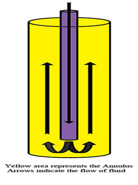 Auxiliary Flow
In special fluid flow designs some customers have requirements for long lengths of fluid transfer.
Shown to the right is an annulus fluid condition. With pipe wall resistance you can get a static flow condition or even in extreme conditions a back flow, or reverse turbulence.
Piping Layout Information
We offer pipe elbows and reducers for the transfer of fluid and slurry. Because of the wide variations of operating and ambient temperatures, fluid condition, pipe size and arrangements, flow characteristics, and junctions it is hard to make precise calculations. With a working layout diagram we can identify and recommend the correct fitting for your system but we do not engineer piping networks.
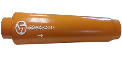
Helix Pipe Reducers
The Helix Pipe reducer is a method for the transfer of liquids or slurry in a pipe structure. The Helix design reduces flow drag and back pressure causing your pumps to work harder and causing additional pump and pipe wear. The Helix pipe reducers are available in sizes starting at 3 inches up to 84 inches. The reducers are a full taper.
Pipe Flow
How Critical is pipe flow in your operation?
It’s a very expensive problem.
Resistance creates excessive pipe wear, additional maintenance, unexpected down time, additional pump wear, and uses more energy to move a given fluid. This is basic pipe flow mechanics.
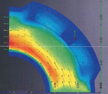
 Fluid Velocity
Fluid velocity is the time and distance it takes to move liquid through a pipe. To the right is a picture showing pipe wall resistance and the energy it takes to overcome that restriction.
Creation of a Vortex:
- Shock angle – This is the point of impact on the leading edge of each Helix fin. It is critical that the first contact point does not interfere with the objective of redirecting the flow of the fluid. This geometry starts the transverse flow. This angle is critical in creating a vortex that gets fully formed as it’s traversing through the controlled rotation.
- Angle of deflection – This is the flow angle caused by the roll of each Helix fin. The number of fins installed, and their pitch angle does focus the fluid to a desired location within the pipe structure. The design of these will be different with various viscosities of fluid but they always are on a symmetrical plane to each other regardless of the fluid’s viscosity. The fluids velocity and centrifugal forces are carefully reviewed with every design of an elbow or flow amplifier.
- Angle of rotation – The angle of rotation is the wrap of each Helix fin through the elbow and most importantly in the flow amplifier. This directs the flow directly through the CL (Center Line) of these components, dramatically reducing all internal sidewall flow resistance. The number of Helix fins creating the flows rotation is directly related to the pipes ID, velocity, and density of the fluid being pumped. This also applies to the degrees of wrap on the pipes ID.
CLICK HERE for additional information about HELIX
Please contact us using one of the options below, or simply filling out our contact form.
PO Box 430
Kalama, WA 98625
800-255-7113